Danfoss FD83 CompatibleDry Break Dual Interlock Quick Coupling Valves
TF83 stainless steel dry break interlock valves are compatible alternatives for selected Danfoss Hansen FD83 configurations. Explore connections for AI data center liquid cooling, CDU interfaces and facility cooling loops.
Compatibility is configuration-specific. Confirm your exact FD83 part number, mating interface, seals and operating conditions before qualification.
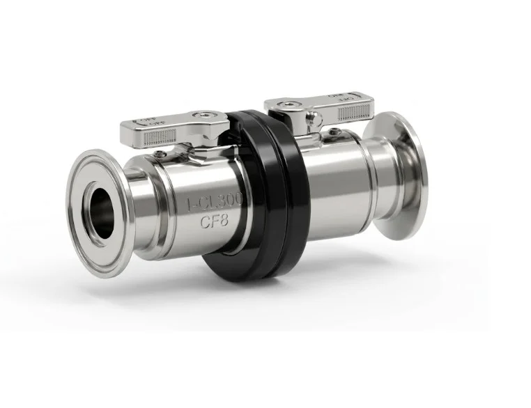
TF83 / Danfoss FD83 Interface Demonstration
Watch the connection, interlock operation and disconnection sequence demonstrated for TF83 and selected Danfoss Hansen FD83 configurations.
Review Your FD83 Interface
Use the demonstration as a reference when discussing an existing FD83 installation or a TF83 replacement project.
- Connection and alignment of the demonstrated mating halves
- Handle operation and interlock sequence
- Controlled disconnection of the demonstrated assembly
The video shows specific configurations. Final interchangeability requires confirmation of the part number, mating geometry, dimensions, seals, fluid, pressure and temperature.
Choose Your End Connection
Start with the interface used in your cooling loop. Confirm nominal size, mating dimensions, seal material and operating requirements for the selected configuration.
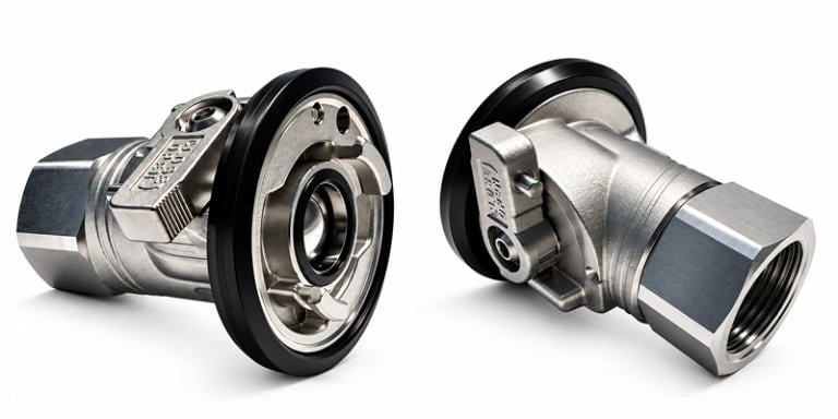 BSPP Thread
Female BSPP Thread Dry Break Quick Coupling Valve
A threaded configuration for equipment and piping interfaces using BSPP connections. Review the port geometry and sealing arrangement with your installation drawing.
- BSPP threaded connection
- Equipment and piping interface review
- Size and seal selection by application
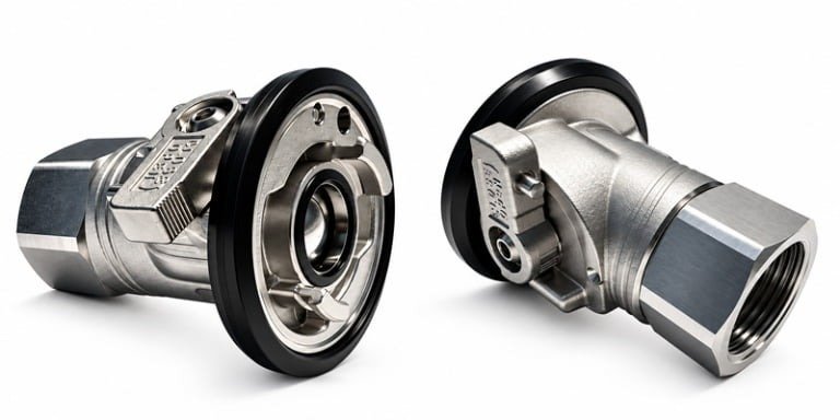 NPT / NPTF Thread
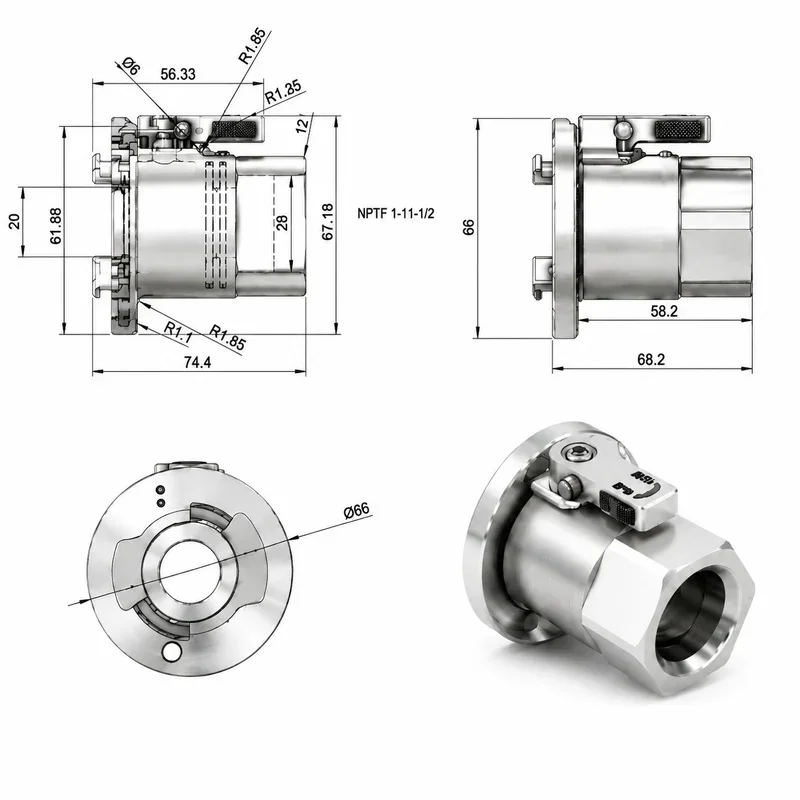
Female NPT Thread Dry Break Quick Coupling Valve
A tapered-thread connection option for cooling mainlines and service interfaces. Specify whether your project requires NPT or NPTF for the selected part.
- NPT / NPTF options by configuration
- Thread specification and installation review
- CDU and cooling loop connections
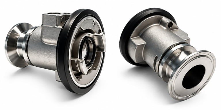 Tri-Clamp Flange
Tri-Clamp Flange Dry Break Quick Coupling Valve
A flange-end configuration for cooling assemblies using tri-clamp interfaces. Confirm ferrule dimensions, clamp selection and gasket compatibility before ordering.
- Tri-clamp connection interface
- Ferrule, clamp and gasket review
- Modular piping and hose assemblies
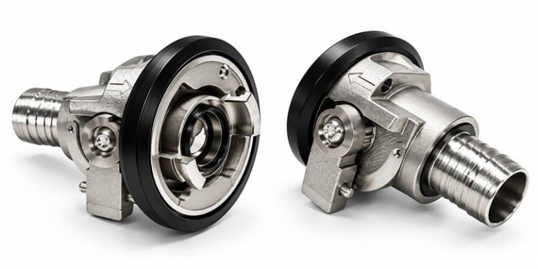 Hose Barb
Hose Barb Dry Break Quick Coupling Valve
A connection option for flexible cooling hose assemblies. Review hose inside diameter, retention method and routing; straight and 90-degree options depend on configuration.
- Flexible hose connection
- Hose dimensions and retention review
- Straight / 90° options by configuration
See the Interlock Sequence
Review connection, handle operation and controlled disconnection in the TF83 demonstration.
Product demonstration; use the operating instructions supplied for your exact configuration.
What to Review Before Installation
- Mating Interface
Check alignment, mating geometry and the required connection position.
- Valve & Interlock Operation
Review the permitted handle sequence and locked positions against the product instructions.
- Isolation & Disconnection
Confirm the required system isolation procedure and size-specific spillage information.
TF83 Reference Specifications
Size-specific reference data from the supplied TF83 product information. Request the current datasheet and test conditions for your selected assembly.
| Parameter | 1″ / DN25 | 2″ / DN50 | 3″ / DN80 |
|---|---|---|---|
| Reference working pressure | 16 bar / 232 psi | 16 bar / 232 psi | 16 bar / 232 psi |
| Reference flow rate | 216 L/min | 899 L/min | 3,240 L/min |
| Reference Cv | 34 | 143 | 520 |
| Maximum reference spillage | 2.8 cc | 11.7 cc | 42.0 cc |
| Design-reference temperature | −20°C to +80°C | −20°C to +80°C | −20°C to +80°C |
- Body material options
- 304 / 316 Stainless Steel
- Seal options
- EPDM / FKM
- Reference working media
- Water / Water-Glycol
Reference values are not a guarantee for every end connection or operating condition. Confirm fluid compatibility, pressure, temperature, flow test conditions and availability for the exact part number.
Connections Across Your Cooling Loop
Select components around the connection size, service access and hydraulic requirements of your installation.
CDU Interfaces
Review inlet and outlet service connections between facility infrastructure and coolant distribution equipment.
Main Cooling Loops
Evaluate larger fluid connections against required flow, pressure drop and maintenance procedures.
Manifold & Hose Assemblies
Match end connections to distribution assemblies, installation space and flexible hose routing.
Evaluating an Existing FD83 Connection?
TF83 configurations can be reviewed for projects using selected Danfoss Hansen FD83 interfaces. Share the exact part number and mating-half details for a configuration-specific assessment.
- Existing part number, photos or drawings
- Mating dimensions and end connection
- Coolant, seals and operating conditions
- Installation envelope and validation requirements
Interchangeability must be confirmed for the selected configuration before qualification or installation.
Danfoss FD83 to TF83 Cross Reference
Find the TF83 catalog configuration corresponding to your existing FD83 part number, body size and end connection.
On mobile, swipe the table horizontally to view all columns. Filters apply to the 12 catalog matches below.
| Danfoss FD83 | TF83 Counterpart | Danfoss Order No. | Body | Port | Thread | End Connection |
|---|---|---|---|---|---|---|
| FD83-2052-16-16 | TF83-2052-16-16 | FD83-2052-16-16 | 1 in | 1 in | 1-11 1/2 | Female NPTF |
| FD83-2046-16-16 | TF83-2046-16-16 | FD83-2046-16-16 | 1 in | 1 in | N/A | 1 in Hose Barb |
| FD83-2092-16-16 | TF83-2092-16-16 | FD83-2092-16-16 | 1 in | 1 in | N/A | 1 in Hose Barb, 90° |
| FD83-2140-16-16 | TF83-2140-16-16 | FD83-2140-16-16 | 1 in | 1 in | G1-11 | Male BSPP, ISO 1179-2 |
| FD83-2126-16-16 | TF83-2126-16-16 | FD83-2126-16-16 | 1 in | 1 in | G1-11 | Female BSPP, ISO 1179-1 |
| FD83-2128-16-16 | TF83-2128-16-16 | FD83-2128-16-16 | 1 in | 1 in | N/A | Sanitary Flange 1 in |
| FD83-2126-32-32 | TF83-2126-32-32 | FD83-2126-32-32 | 2 in | 2 in | G2-11 | Female BSPP, ISO 1179-1 |
| FD83-2046-32-32 | TF83-2046-32-32 | 11349026 | 2 in | 2 in | N/A | 2 in Hose Barb |
| FD83-2128-32-32 | TF83-2128-32-32 | FD83-2128-32-32 | 2 in | 2 in | N/A | Sanitary Flange 2 in |
| FD83-2052-32-32 | TF83-2052-32-32 | FD83-2052-32-32 | 2 in | 2 in | 2-11 1/2 | Female NPT |
| FD83-2092-32-32 | TF83-2092-32-32 | 11358296 | 2 in | 2 in | N/A | 2 in Hose Barb, 90° |
| FD83-2175-32-32 | TF83-2175-32-32 | 11369532 | 2 in | 2 in | G2-11 | Male BSPP, ISO 1179-3 |
No matching catalog configuration was found. Try another part number or connection term, or send your details for review.
View Reference Installation Dimensions
Dimensions reproduced from the supplied reference table. Use the drawing for the selected configuration to identify A, B and hex dimensions; confirm the latest revision before installation.
| TF83 Part Number | End Connection | A (mm) | B (mm) | Hex (mm) |
|---|---|---|---|---|
| TF83-2052-16-16 | Female NPTF | 95.5 | 71.6 | 41 |
| TF83-2046-16-16 | 1 in Hose Barb | 84.2 | 71.6 | — |
| TF83-2092-16-16 | 1 in Hose Barb, 90° | 142.3 | 71.6 | — |
| TF83-2140-16-16 | Male BSPP, ISO 1179-2 | 95.5 | 71.6 | 41 |
| TF83-2126-16-16 | Female BSPP, ISO 1179-1 | 84.3 | 71.6 | 41 |
| TF83-2128-16-16 | Sanitary Flange 1 in | 79.6 | 71.6 | — |
| TF83-2126-32-32 | Female BSPP, ISO 1179-1 | 112.0 | 105.3 | 70 |
| TF83-2046-32-32 | 2 in Hose Barb | 156.8 | 105.3 | — |
| TF83-2128-32-32 | Sanitary Flange 2 in | 102.4 | 105.3 | — |
| TF83-2052-32-32 | Female NPT | 112.6 | 105.3 | 70 |
| TF83-2092-32-32 | 2 in Hose Barb, 90° | 155.2 | 105.3 | — |
| TF83-2175-32-32 | Male BSPP, ISO 1179-3 | 134.3 | 105.3 | 75 |
8 FD83 Variants Requiring Custom Review
These configurations appear in the supplied reference but do not have a standard one-to-one TF83 part number in that table. Submit the FD83 code and application details for review.
| Danfoss FD83 | Order No. | Body | Port | Thread | End Connection | TF83 Status |
|---|---|---|---|---|---|---|
| FD83-2052-12-16 | FD83-2052-12-16 | 1 in | 3/4 in | 3/4-14 | Female NPTF | Custom review |
| FD83-2096-16-16 | FD83-2096-16-16 | 1 in | 1 in | 1 5/16-12 | Male ORB, ISO 11926-3 | Custom review |
| FD83-2046-24-32 | 11349477 | 2 in | 1 1/2 in | N/A | 1 1/2 in Hose Barb | Custom review |
| FD83-2046-20-32 | 11349492 | 2 in | 1 1/4 in | N/A | 1 1/4 in Hose Barb | Custom review |
| FD83-2170-16-16 | 11367128 | 1 in | 1 in | N/A | 1 in 1G Crimp | Custom review |
| FD83-2168-16-16 | 11367142 | 1 in | 1 in | N/A | 1 in 1G Crimp | Custom review |
| FD83-2170-32-32 | 11367130 | 2 in | 2 in | N/A | 2 in 1G Crimp | Custom review |
| FD83-2168-32-32 | 11367129 | 2 in | 2 in | N/A | 2 in 1G Crimp | Custom review |
Reference basis: the supplied TF83 / FD83 catalog cross-reference table. Order numbers and dimensions are reproduced as provided; confirm current product documentation when selecting a part.
Frequently Asked Questions
What does dry break mean?
A dry break coupling uses a valve-equipped interface to isolate the fluid path during disconnection and limit released coolant. Spillage varies by size and operating conditions; dry break does not mean zero spillage in every situation.
What should I confirm about the dual interlock design?
Request the operating instructions for your selected TF83 configuration. Review the valve-opening, locking and release sequence, along with system isolation requirements, during engineering qualification.
Which sizes and end connections can I request?
The supplied TF83 information lists 1″, 2″ and 3″ reference sizes, with BSPP, NPT / NPTF, tri-clamp flange and hose-barb configurations. Confirm the available size and end-connection combination when requesting a quote.
Can these valves be used with water-glycol coolant?
Water and water-glycol are listed as reference working media. Share the coolant formulation, concentration, temperature and pressure so the body material and EPDM or FKM seal selection can be reviewed.
Are all TF83 configurations interchangeable with FD83?
Compatibility is configuration-specific. The exact part number, mating geometry, dimensions, materials, seals and operating requirements must be assessed before approving a replacement.
Can I request drawings, samples or a custom connection?
Include your required configuration, quantity, drawing and qualification needs in the inquiry. Availability, customization scope and project timing are confirmed during quotation.
Discuss Your Liquid Cooling Project
Tell us your coupling size, end connection, coolant, operating conditions and quantity. Include your FD83 part number for a compatibility review.